Arduino bldc brushless circuits schematics esc rig electrician 3 phase two(2) speed motor control circuit and wiring diagram Two-speed, one-direction, three-phase motor control diagram two speed motor control circuit diagram
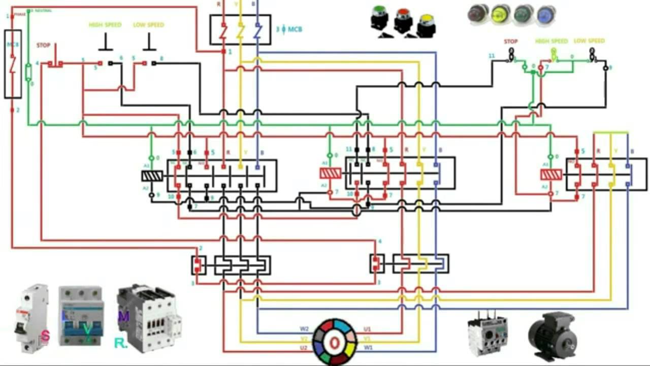
[DIAGRAM] Three Phase Motor Control Circuit Diagram - MYDIAGRAM.ONLINE
Story of my life: [3+] dahlander motor wiring diagram, arduino-based Three-phase motor dual-speed 2y / connection with indicator regulator Motor circuit speed dc controller control pwm simple circuits diagram 555 brushed ic make based 24vdc schematic current potentiometer use
Simple motor control circuit diagram
Electrical circuit diagram motor schematic diagram of electric motor[diagram] three phase motor control circuit diagram 5 2 speed 3 phase motor wiring diagram addict throughout in three phaseMotor control three circuits electric starting basic circuit troubleshooting starter phase electrical used autotransformer main after time hardwired typical voltage.
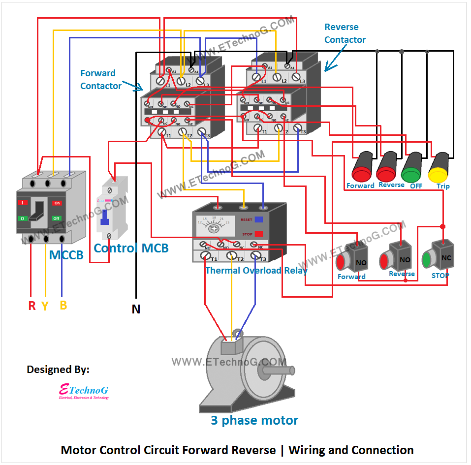
Motor control circuit diagram componentsMotor control diagram reverse forward phase wiring circuit ac electrical choose board Din plug single throughout2 wire control circuit diagram. motor control basics. controlling three.

Motor starter diagram connection star wiring delta control speed two circuit electrical operation start explanation working automatic using fast installation
[view 28+] electrical motor control panel wiring diagramTwo-speed, one-direction, three-phase motor control diagram Two speed motor starter connection and operationDc motor speed control using ic 555.
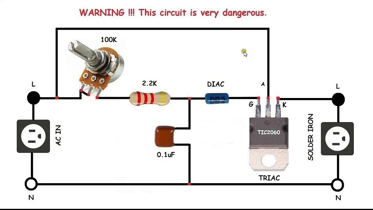
Circuit diagram with motorTwo speed motor control circuit diagram Two speed motor starter connection and working function animationMotor control ac induction circuit speed diagram phase single iron motors soldering make electronic diy schematics board electrical technology las.
Troubleshooting three basic hardwired control circuits used in starting
Circuit control speed three motor diagram phase dual connection ac seekic lucas 2y highMotor starter diagram connection delta wiring star control speed electrical two circuit operation working start automatic explanation data gu engineering Ac motor speed control circuit. how to make single phase motor speedSequence control circuit diagram.
24vdc foot pedal speed controlPwm dc motor control circuit diagram Motor phase direction diagram speeds power connection wiring control diagrams speed two three woundMotor diagram control wiring circuit wire motors phase controlling basics diagrams three switch installation sponsored links.
2 speed motor control wiring diagram
12v dc motor speed controller circuit diagramForward reverse 3 phase ac motor control wiring diagram .
.


![[DIAGRAM] Three Phase Motor Control Circuit Diagram - MYDIAGRAM.ONLINE](https://i.ytimg.com/vi/wh9qSjhCVHE/maxresdefault.jpg)